Go Kart Steering Systems
Be sure to watch the video on the importance of Over Steer and Under Steer….
You have probably ridden or seen a go kart and wondered how all those linkages make the go kart turn. The system can look like a plate of spaghetti at first, but once understood the system is quite simple and ingenious.
First the purpose of the steering system, obviously, is to turn the go kart. But the not so obvious part is turning the go kart without causing surging and tire squealing. The geometrical relationship between the go kart line of action and the turn radius are important for a smooth turn and even tire wear.
Steering systems can be classified into two different designs:
The Ackermann steering system
The Bogie Steering system
We will start with the Bogie system because it is the most efficient and simplest in design.
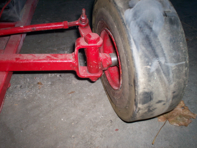
The bogie system is where the two front wheels are mounted on a beam or the same axel and pivot in the center section. I call it the wagon style steering system, because it is very similar to the system found on simple pull behind wagons. The handle, for example on the pull behind wagon, directs the front wheel system and changes the direction of the wagon.
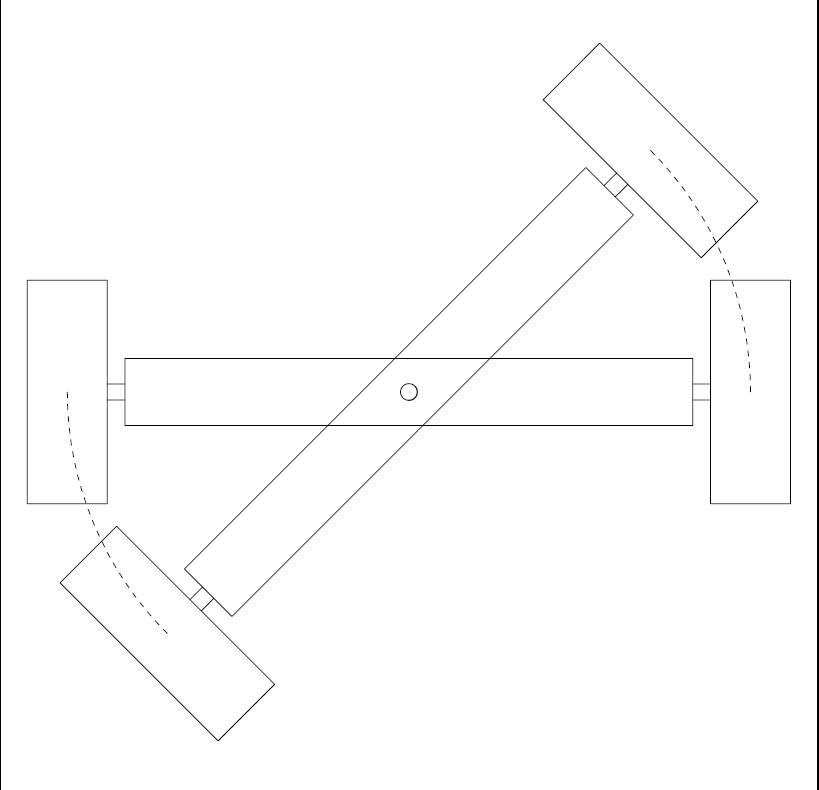
This system is most efficient because the wheels uniform ally scrub the same when the vehicle is turned and the follow the turn center, or turn circle in the correct geometrical relationship.
You may have gotten lost on that last statement, not to worry, we will reflect on that later. It is just important enough to know that the wagon style steering has its place.
The downside to typical wagon style steering is that the amount of movement required to make the gokart turn can be quite large. A sweep for example of over 60 degrees is typical which can amount to being around 18 inches of movement from extreme positions (full left to full right turn) on a typical go kart. To achieve the rapid movement of the bogie system can be difficult to attain without creating excessive loading (or arm strength required, which can be a challenge for younger drivers) and or excessive steering wheel movement (multiple turns of the wheel, which most go karts do not require.)
Another design consideration of the bogie system is that it must be supported. The front wheels need to provide vertical support during a turn or other wise the go kart can flip. To accomplish this the front steering is supported by the framework above it to keep the steering from rising up during turns.
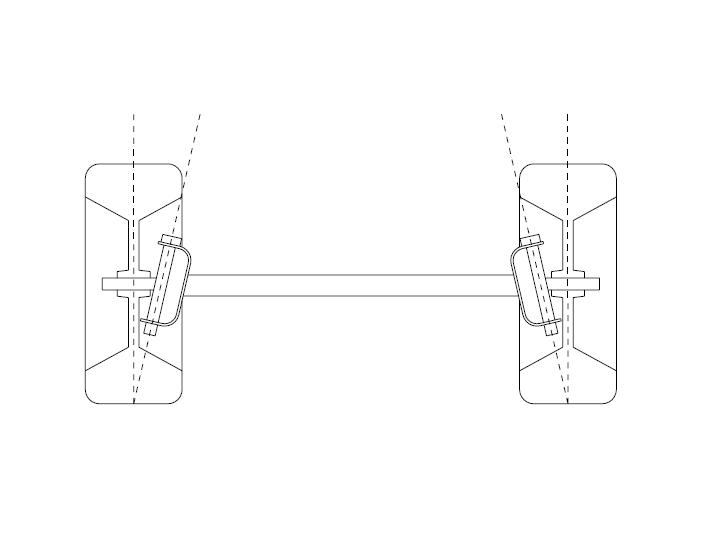
The Ackermann steering system or the steering knuckles system is where the axles are mounted on knuckles out and away from the go kart. The wheels rotate vertically around these pivots, and cause the wheels to turn.
There is a relationship in the wheels movement to a turned center. There is also a positioning system on the steering knuckles which is important for steering. The positioning system is more important when applied to heavier vehicles. For lighter vehicles, like go karts, the positioning is not as important.
If you are seriously going to make a go kart, I would highly recommend that you go to the steering knuckle system.
That said; let us discuss in further details the steering knuckle system.
There are a couple of things that we need to identify: there is a turn center, and vehicle radius turn centers.
The hardest part to envision here is that the inside wheel is trying to spin slower than the outside wheel. And that by definition means that the radius of turning for the inside wheel is going to be smaller than the outside wheels turning radius.
The best way to explain this is in the example of a merry-go-round. If you get on a merry-go-round while it is spinning and you were to go to the center area, you would notice that it is not spinning as fast in the center. You will feel less pulling energy. But as you go to the out side you will feel yourself being yanked out. The reason for this is that you are feeling more velocity or energy. The outside of the merry-go-round goes faster than the center. Even though everything is spinning the same, the velocity at the radial point you are at increases as the radius increases. The velocity at the outside of the merry go round is higher and will cause you to feel more force and wind speed on your face.
And that is the same thing that is happening with a go-kart when it is turning, the outside wheels will spin faster than the inside wheels. (Just as a side note: the differential on a car is designed to accommodate the different speeds of the outside verses the inside wheel. So that the outside wheel spins faster than the inside wheel.)
On a go-kart however, because of the small turn radius, the inside tire will chirp, or loose traction because it is trying to go as fast as the outside tire. In other words the inside tire will be going the same rotational speed in a turn as the outside wheel. This will cause the tire to spin or loose rubber when the gokart is turned. That is where the wear comes from. It is primarily coming from corners. Because the outside wheel is spinning faster than the inside wheel would like to go.
Keeping that in mind, the steering mechanism on a go-kart needs to accommodate the differences in tire speeds to maximize the effectiveness in cornering.
The Turning Point
In order to get a tire to turn well or easily, the tire needs to turn around the turning point. The intent of the design, is to turn around the center of the tire.
When you think about that, there is less scrubbing action. It is a lot easier to exert forces into, or move the tire in the vertical axial motion. If you were to do some examining of wheels on cars, and how they are set up, you will see the tires will spin around their centers. And in doing so, it is easier on the tires, it is easier on the suspension system, it is easier on the drive line, and it is easier to move the steering wheel.
Four wheel drive trucks have difficulty in their designs to get the front wheels to have the turning point at their centers. The design encounters some mental gymnastics to get to that ideal positioning. If you look at trucks for instance they have this issue. What four wheel drive trucks will do is make the hub stick out a lot farther because they are trying to get the turn’s center to be right at the center of the tire.
There is another element in the Ackerman steering , which is the incline of the turning or caster. The design of the incline of the turning system has to do with the forces that the vehicle encounters during turning. If the system is leaned back towards the back of the vehicle, the steering will be more advantageous, more aggressive. Also the forces exerted by the vehicle are reduced. The vehicle has less affect over the steering wheel and there is a more commanding feel on the steering wheel than the vehicle does on the occupant. That is the main purpose of castering the steering system.
It is generally incorrect to design a vehicle so that the wheels will not turn ideally on the turn center. The result is that the tires will exert higher push back and scrubbing forces which will be felt in the steering wheel.
As a driver you’ll be fighting the steering wheel more just to drive the go kart.
Consequently, you will have to keep that in mind, if you are designing a go kart with really big tires. The big tires will be heavy. If the vehicle steering system is not designed correctly, the driver will be fighting hard to make steering movements. It will not be an enjoyable ride.
A ways to get around a poor steering system, would be to have a rack and pinion steering, which helps to gain mechanical advantage. In other words, it makes steering less difficult, by making the resistance of the turning less.
The way to get around having a complex rack and pinion steering system, is to design the steering system correctly with the steering point in the correct spot, the ackermann relationship optimized, the castor set for maximum effect and the camber for maximum turning power. It does take some ingenuity, and design layout to accomplish those goals.
To keep this in perspective, engineers devote their lifes to designing suspension systems for cars. That is all they do.
To expect yourself to design something right off the bat, it is kind of a lot to expect. One way to get around that is to buy someone’s plans where they have performed all those calculations, and they have done it already. Or you can use the rough guidelines I’ve talked about. You can do some rough layouts and try to figure out a little bit. In the Go Kart Building Series, there are further details on how to design steering systems. This is a great resource, especially for those who want to do it right.
The Steering System Design
The Ackerman steering system consists of levers that are put onto each one of the steering knuckles. The length of the lever dictates movement and force required: the longer the lever, the better the mechanical advantage. However, the longer the lever, the more throw is required. And of the more throw that is required, then the more expensive the steering system.
The low cost ideal solution for a go kart is equal length systems on steering drive and on steering knuckles. They are going to be roughly about the same radial distances. The system is essentially a parallelogram system. Which results in an equivalent amount of movement in the steering wheel and in the wheel knuckles as they are turning.
The design of the Phi-Alpha-10 for example, has the inside wheels turning more, as the outside wheels turn less. It has to do with the offset of the rod mounts on the steering drive. The system would be clasified as a four bar linkage. The layout can be roughly done on a piece of paper or on a mechanical design program. The radial turn relationships can then be layed out as well to help optimize and visualiz the system.
You may have seen systems where the tie rod ends join in at the same point. Joining the two rod ends at the same point is not ideal, but it is not going to be a problem on a go kart either. The purpose for the four bar linkage system is because the steering radius can be optimized more with the four bar linkage system. It has to do with the width of the go kart. The system geometry for example is going to be slightly different for a double wide go kart than for a single width go kart.
From a go kart perspective (unless you are making a racing go kart) the system will probably work fine. The only time the system will exhibit issues is during extreme cornering. The results will be tire scrub, most notably hunting from inside to outside tire, depending on the pavement type. Joining the tie rod ends together on one pin at the steering drive is not ideal, however, and will function properly, just not optimally. The fourbar linkage is more ideal, or to have the rods offset, as are in the Phi-Alpha-10 and Phi-Alpha-9 plans. A four bar linkage design works better and has been proven out. A lot of race go-kart designs use this offset for bar linkage design.
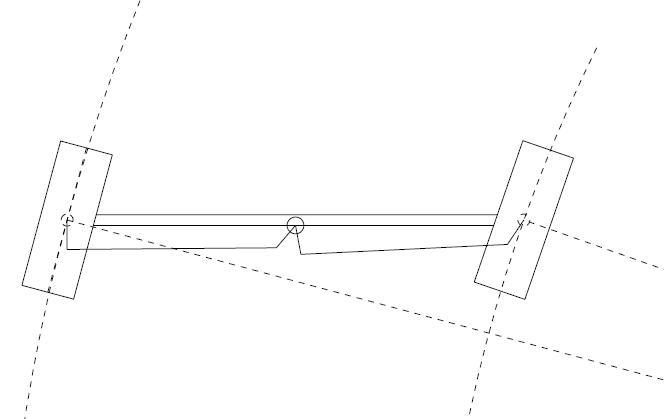
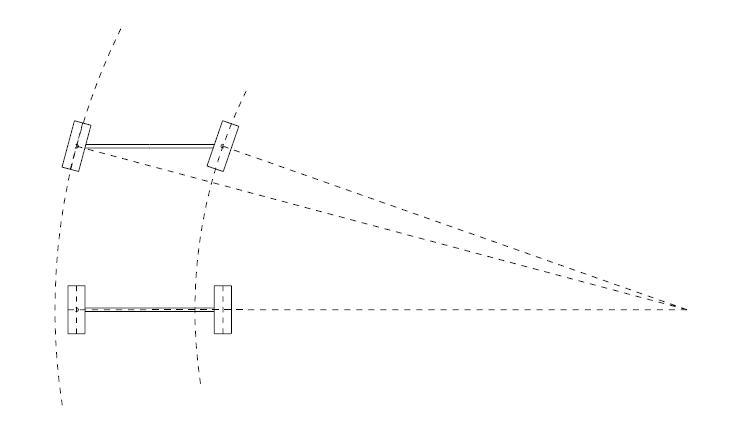
Figure: Outside Wheel Has Less of an angle (15 deg) where as the inside wheel has a steeper angle (19 deg). Notice the two different radial turning paths for each tire. The outside has a larger radius and the inside a smaller radius. The outside must go faster to keep up with the inside tire.
Now, the question is “Do I put the tie rods above or below the steering system?” I prefer, to go below. And the reason for that is, your feet can get above the steering mechanism. They are not getting going to get all tangled up in the tie rods. There are plans, and I have seen it were the steering mechanism is above. Unfortunately the drivers pants and feet get tangled up in the tie rods. As a result the design for the Phi-Alpha-10 and Phi-Alpha-9 have the tie rods below from a packaging standpoint.
Suspension Systems
One thing to keep in mind, especially on a suspension system, is that the relationship of the steering tie rod ends can change when the suspension moves. If the system is not designed correctly, (in other words if the center lines of the steering tie rod ends are not right in the center, as in a parallelogram system) when a bump is encountered and the wheel goes up, the wheel will either move in or out (axially vertically). The relationship between the wheels and the steering system will change causing the front wheels to flop back and forth. That can be very dangerous when the vehicle is moving.
The tie rods must be in a neutral position as the suspension moves. The result will be so that the wheels are not turning vertically when the suspension moves. This design step is pretty important.
If you look at a car, and examine its suspension system you will see that the tie rod ends and their relationship to the suspension does not move. They maintain a central position which is very important for, obviously tracking. Imagine if you were to put a load, a front load with someone who is heavier than you, and all of a sudden the tracking of the wheels is off because the suspension tie rod ends relationship is not neutralized or correct.
The steering knuckle system is by far the most reliable, most robust and most controllable system that go carts use, and cars use for that matter. As far as the steering knuckle designs are concerned, there are a whole host of different ways to hold steering knuckles in place.
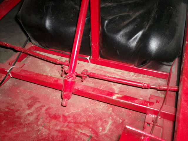
A simple system is to use a tube with a very large bolt welded to the tube. The tube is then surrounded with a C-channel. Then run a bolt through both the C-Channel and the tube. On the tube itself weld a radial arm. On the arm itself should be a gusset, so that it maintains twisting motions when bumps are encountered. On the arm have a hole to mount the tie rod end. The tie rod links up over to the steering drive system. The steering rods goes out towards the passenger. Both sides of the systems link to the center steering drive system.
A tie rod end is moving joint that has a ball in it. The tie rod can move and about 360° in motion in two planes. The rod end can move the rod back and forth. It is designed to transfer the load from the steering drive system to the steering knuckle.
The steering parts can purchased as units at any go-kart supply house. https://gokartguru.com/partsupplies.php
There are different kinds of tie rod ends that can be used.
There is a rod with a thread, where the steering rod end threads into the tie rod end. An important and often ignored design consideration is that the tie rod ends can become loose.
Because a go kart is a vibrating machine, everything needs to be tight or it will prematurely wear out and eventually fail.
To keep a tie rod end tight, jam nut the tie rod end. This keeps everything nice and tight.
It is very important that all joints be relatively tight and not loose, because vibration will start to make things fail, bend and wallow out. Eventually the steering system will be off, and will have lots of vibration. Even if a very large motor is mounted and vibrates a lot, as long as the steering system is pretty tight the tie rod ends will maintain tightness. Even if vibration comes up the steering column, tight tie rod ends will maintain their positioning. If things are loose then the steering knuckles will wallow out. The tire will wear out more quickly as well.
Now one word on adjustment of the steering system. I have noted that some go-kart places denote that the front wheels should cant in forward 1°. Or 1° negative tow.
The reasoning for that is: that when the go-kart goes forward the slop is taken up, and all wheels will be parallel. So it is a good idea to put at least 1° forward. It will wallow itself out when you start driving. It also has to do with the amount of bite you get when you steer.