| “How to Build a Go Kart?” What a great question. The answer to that question is not that complicated but it does require some thought. The “How to Build a Go Cart” process involves seven different steps, they are:
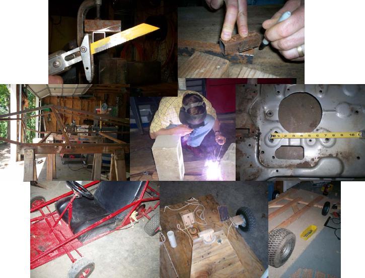
– Finishing touches Go Kart PlanWe have over 11 E-books on How To Build a Go Kart. The go kart plan does not have to be that complicated it just involves knowledge about drive systems and the center of gravity relative to the performance of the go cart itself. The center of gravity comes in to play when the go kart corners. The way the go kart actually moves or is acted upon by the forces of nature is dictated by where the center of gravity is located on the go kart. The ideal location of the center of gravity is what is called 50-50 weight distribution. A good go kart plan will take that into account. Additionally a good go kart plan will show how to make a go kart strong, safe, and easy-to-use (construct or follow). There are a whole wide variety of go kart plans on the Internet. Some are free, and some can be purchased. Typically the price of the go kart plan is relative to the quality of the actual product. The design of the go kart hinges upon the go kart plan. All the drive systems, steering systems, the brake systems, and the seating systems are all interrelated and all affect the center of gravity and the overall performance of the go kart. On this webpage we do supply a go kart plans, but we also supply books that show how to develop a good go kart plan, or a go kart frame. Like I said before a go kart plan is much more than just a frame it also involves the drive system, brake system, throttle system, seating system and safety considerations. On this website we are seeking to help you make a go kart that you would be proud of, that does not look like a piece of junk, that actually performs pretty well. We have over 11 e-books currently available that are all designed around different parts of the go kart. The go kart plans come free with the Go Kart Building Bundle and the Mega Bundle. Welding up the go kart frameWelding of the go kart frame requires that the parts be relatively square to one another. The reason for this is that he want all four wheels to be touching the ground and secondly you do not want the go kart ride sideways but to ride straight. Maintaining squareness and parallel is accomplished by a variety of means, the easiest way is to use simple boards and clamps. Ideally use of a very flat garage floor helps out a lot in that the flatness of the go kart frame can be maintained by the floor. Basically what is required is that the two sides of the go kart are fabricated then the two sides are joined together by the horizontal members. The frame then it is tacked together; then fully welded after the whole design has been checked for squareness and flatness. The actual fabrication of the frame is accomplished by simple cutting of tubing that is joined together squarely, so that is easily welded together. The tubing of the go kart can be made of 1 inch square .100 thick walled tube. Use of square tube verus round tube is acceptable. Square tube is actually easier to deal with and to keep square and to align. Additionally square tube is easier to mount accessories and bracketry. (Be sure to read the article on angle iron versus tubing.) There are wide variety of welders available on the market, but all that is really needed is 110 volt welder. A simple stick welder is all that is required. I recommend using a jigsaw fit it with a metal cutting blade. If you have a saws-all it works beautifully when a metal cutting blade is mounted to it. Additionally, a vice is almost a must have for making a go kart. Go kart building 401 (Frame Welding and Fabrication) goes into all sorts of details about fixturing, and what type of tools to use. It also gives you tips on how to cut time in fabricating your go kart. Once the frame has been welded up, the rear-drive system can be mounted to the framework. I prefer a live axle system. Basically the bearing holders, which are usually flat plates, are fixed to the framework and tacked in place. The go kart frame is held in the air or spaced into the air with two by fours. The rear axle with wheels mounted to it is then fitted into the frame-bearing holders. The overall squareness of the rear axle in three planes is checked. Make sure the rear wheels look square to the frame, that the frame does not look crooked or set higher on one side than the other, then tack weld the bearing brackets in place. The engine plate then is tacked in place as well, and the engine is placed onto the engine plate. At this point do not drill any holes for the engine just place the engine in place with a chain and the rear sprocket system layout. Place the engine in the ideal location, check for clearances, for squareness, for best tracking and then spray a little spray paint into the holes on the engine mount area. Leave the engine in place for about 10 minutes, then remove the engine and drill in the paint spot areas. Make sure that you drill smack dab in the center of the paint spot. Drill holes which are identical in size as the engine mount holes. The reason for this is that the engine will maintain position and not cause the chain to come off because of poor tracking. Be sure the chain is tracking well and that there is clearance for the bottom catenary section. The go carts that I designed have a difference in that the engine is not mounted on a slot track. The chain slack is taken up with a chain tensionor which is made up of readily available materials. The go kart plans go into details on how to make the chain tension or an out of layout go kart track system for optimum center of gravity placement. Once the drive system has been established then the engine plate can be welded complete into place. One thing of note is that you may not want to weld the motor plate so solid that you can never move it. So you may want to skip weld (not fully weld the seams) and make it easy to grind off welds later. A word about vertical engines and drive systems:Vertical engines have their own set of rules and their own set of drive systems. Typical drive systems for vertical engines are not that complicated, however, they do require a simple understanding of ratios. Make sure the go kart engine drive calculations have been performed prior to committing to a drive layout. One of the serious mistakes most go carters make is that they take hold of components and assume they are going to work. This can be a fatal mistake in that the go kart can be set up and incorrectly and will stall the engine, smoke a clutch, and not drive very well at all. In the go kart building 201 and 202 courses we discuss how to set up a drive system so that the engine and the go kart are matched, and we also show how to set up a vertical engine drive system without having to do extensive engine modifications. Placing the steering systemThe steering system is designed using conventional linkage relationships better known as the Ackermann steering system, however, the steering system additionally, is designed to be both ergonomic (meaning well-placed and easy to steer, comfortable) and functional. That may sound like a lot of gobbledygook but the bottom line is that the steering system must turn a go kart effectively and be comfortable. The Ackermann steering system causes the relationship between the tires to be uniform and grip properly during cornering events. Additional enhancements to the steering system are possible such as Castor and Chamber. Castor and Chamber are fancy ways of enhancing steering performance from a tire attack angle and steering force maginitude. Placement of the steering is based on the 50-50 weight distribution calculations which were performed earlier. A simple way to establish 50-50 weight distribution is through weighing the go kart. Weighing the go cart at this point involves all the components that are part of the go cart system. This also includes the person, or persons. The calculation is performed using simple balance equation’s which are explained in the go kart building 301 book. The exact equations for developing center of gravity are derived in this book. We do however offer a resource (center of gravity program) which is on our webpage which actually calculates the center of gravity for your go kart. All that is required is that the weights of each component be fitted into the program. What the program will tell you is where your steering system should be placed. The easy way to assess the center of gravity on the go kart, however, is to add all the components together physically by weighing them using a scale. The position of the rear wheels is fixed and thus the scale is fitted underneath the rear wheels first. Then the scale is fitted underneath the front section where the front wheels would be mounted. The two weights should be really close to each other. What this means is that you have the same weight on the front as you have on the rear wheels. This is known as 50-50 weight distribution. A little word on 50-50 weight distribution:50-50 weight distribution gives you the best scenario for steering. Instead of having the rear end kicked out so bad when going around the corner or having a go kart just go straight and hit things when trying to go around the corner, the 50-50 weight distribution maximizes cornering and gives you the best of both worlds in steering. Instead of having oversteer or understeer you have a combination. The whole concept of steering is discussed in our steering book and goes into greater detail about the effects of oversteer versus understeer. There are also other resources available on the Internet that explain steering systems. The steering book comes with the bundles sold on this website. The position of the steering wheel is based on personal taste. However the ideal location of the steering wheel is so that the arms are comfortable or can be maintained in that position for relatively long periods of time without exhaustion. The steering wheel position should be experimented with by holding the steering wheel in positions which feel comfortable. Meaure these positions, take pictures of these positions, and then place them into the go kart while sitting in a go kart. Be sure to be happy with the steering position before committing to the final design. I recommend tack welding the placement of the steering system in place and testing it multiple times. Do not be afraid to cut the welds and start over again. Placing the seatWe had just mentioned the placement of the steering system, sometimes the placement of the seat can proceed before putting the steering system into place. They both are interrelated so placing the seat before the steering system is not an issue it may actually help place the steering wheel better. However placing the steering system first can make it easier for making your seat because you may have design around the steering system. Keep this in mind when you’re designing your seat and your steering system. The seating system is made of relatively available materials such as plywood, cushioning, vinyl. Be sure to round off all edges on the plywood so is willl not tear into the fabric. The use of simple staples and is recommend. If you are feeling making your own seat is a lot of work you can purchase a seat however, the cost of buying a seat that is comfortable may end up blowing the budget for this go kart. Remember we’re trying to make a go kart out of junk and for less than $200 so buying a lot of extra stuff makes a go kart expensive. The go cart seat is mounted to the frame using wood screws or bracketry. One key note about the rear back is that the retention of the seat should be made so that it can come off easily. The reason for this is easy access to the engine, which may be necessary for overhauls and even simple oil changes. There are a whole host of reasons for this seat and why it is designed away is these are reviewed and the go kart building 501 book where it goes into details on how to actually make a seat so that it keeps you in while cornering. There are reasons for the seat being tall, being soft, being supported, and being made out of plywood. Most of these reasons are based on safety and performance. Mounting The Brake SystemThe brake system comes in a variety of forms they are: -The rubbing break These brake systems are the most common systems used on go carts. In the go kart building 302 course it goes into details on how to actually calculate the brake forces. On the wood go kart for example there is a rubbing brake. The actual rubbing brake system, however, is not just a simple board. He requires mechanical advantage so that the force of a foot can actually press on the wheel by 10 to 15 times the force. One key to understanding brake systems is that they should float. The reason for this is that you do not want a rubbing brake. A rubbing brake, obviously means the brake will wear out quicker. This needs to be taken into account when the brake is mounted to the frame. Something has to float, the disc, or the brake system. Actuation of the brake system is accomplished through cabling. The return springing of the foot pedal is accomplished through springs mounted either at the pedal or at the brake system in the rear. A redundant system of two springs is preferred. Mounting of the pedals is accomplished through plates mounted to the frame. Adjustment of the pedals makes the frame that much more versatile. The versatility comes into play when you have a tall driver versus a short driver. The pedal can be moved either forward or backwards with a simple unbolt and re-bolt. A positive stop to the pedal in the retract position is recommended so that the pedal does not flop back on itself. A simple plate of steel will do the job. Make sure the pedal is comfortable to actuate in the seating position. The layout for adjustable pedals with positive stops is detailed in the go kart plans sold on this web site. Mounting the throttle systemThe throttle system typically uses lightweight bicycle cabling. Bicycle cabling from a brake system or a gear switching system is usable. Remember the cable is just a medium of exchange, it is not the primary and engager. What I mean by that is you cannot push a cable, you can only pull on it. So constant tension is required in the cable to make it work properly. Positioning of the cable, and retention of the cable is an important consideration and can be difficult if not performed properly. In the go kart building 302 course we discuss how to actually mount the throttle cable into a system that allows different style engines to be easily retrofitted into the go kart. This can be a big bonus especially one a Briggs & Stratton has a different throttle systems than Tecumseh. What is important to a throttle system is a return spring. The throttle must be disengaged when the foot pedal is released. This may sound very simple, but one of the biggest dangers on a go kart is a wide open throttle that is stuck open. This can be very dangerous and very alarming. Make sure the throttle is positively sprung shut is a linkage work to break off of the throttle. Again the pedals are mounted so they can be moved into various positions. This helps with smaller drivers, and larger drivers. Positive disengagement, or positive release of the pedal is a plus and can be accomplished using simple metal plates. A word about pedals: The Finishing TouchesThe finishing touches entail mounting the bottom plate, mounting the on-off switch, and painting the go kart. The mounting of the bottom plate is accomplished by fitting a piece of sheet metal, such as used in the heat duct work, on the bottom of the go kart. The retention of the go kart plate is accomplished using self tapper screws. A simple drill can zip the screws into place. I preferred the self tapper screws that have a drill bit on the end. Be sure to fold over the sharp edges of the sheet metal so that cuts cannot occur by minor brushes against the go kart. The on-off switch, is typically mounted, in the center of the steering wheel. All that is required is a single wire fed to the ignition module on the go kart engine. When this ignition wire is grounded the go kart engine stops running. The go kart switch grounds itself through the framework into the engine. So all that is required is one wire from the switch to the frame and then another wire to the engine. Painting the go kart is best performed by scraping all the rust and all the grime off of the frame. Obviously the go cart must be disassembled and all the parts taken apart. Simple masking can be done, however, it is best to paint all exposed metal parts. Priming the frame is a good idea, because the primer actually bites better than paint. The primer acts as an adhesive for the paint. A simple enamel paint does the job. If you ride your go kart frequently every summer, you will need to paint your go kart every two years. The reason for this is that the pain will chip, especially from rocks. |
Great Birthday Present
The Father and Son
Wood Go Kart Project
Any Occasion Gift Idea
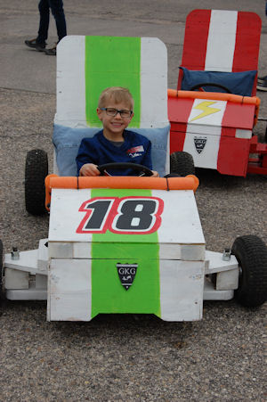
The Ethan Speedster Go Kart
From the Movie
"God Bless the Broken Road"