Super Charger Performance Upgrades
Intercooling
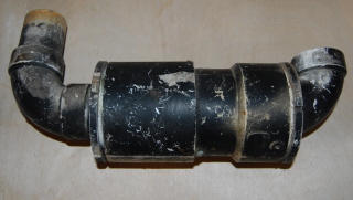
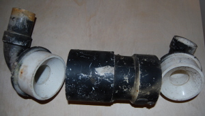
A simple intercooler for a supercharger set up using pvc pipe sections
Intercooling is a means of removing the heat energy that’s been developed by the compressor on the air that is being rammed into the engine. The heat energy that is generated by the compressor causes the density of the air to actually decrease. What this means to an engine is that you’re not actually ramming as much air in as you like. When the density of the air decreases the amount of air fuel that gets into the engine is not as great as what was desired. The net effect is that the engine does not increase in power but may actually lag in power. This is especially prevalent in engines that have belt driven superchargers. Also with a turbo supercharger the air actually can get heated up because the turbine itself is heated by the exhaust gases.
Intercooling can also be used on normally aspirated engines to gain horsepower as well. The desire is to get more air into the engine and intercooling the air causes the air to become more dense and therefore have more air fuel per intake stroke.
 Intercooling is achieved by feeding the air through a series of veins that are cooled down by either air passing over them or by having the veins packed on ice or water.
A cheap intercooler can be developed by constructing multi-channels for the air to run through and then surrounding these channels by a cold water jacket. Below is a simple supercharger that was developed using PVC pipe and copper tubing.
Additionally, cooling can be achieved by putting water jackets around the intake manifolds to keep the intake air colder as well. This helps especially in engines that are prone to heat up during hard running. Development of these particular water jackets can be quite a challenge. See the watercooled intake manifold below.
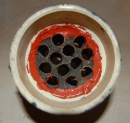
The Intercooler Tubes are surrounded by cold water. The air passing through them cools down.
Pressurization
When the supercharger is trying to ram air into an engine had also needs to bring fuel into the engine as well. Before we had mentioned that the means towards getting the air fuel into the engine is through carburetion either by sucking the air through the supercharger or ramming air through the supercharger. In order for air to be rammed through a carburetor the carburetor itself must be pressurized.
What this means is that the normal function of the carburetor must not be interfered with. A carburetor operates on the principle of vacuum and once you introduce into the carburetor a higher pressure than the net effect is that the gasoline will be shoved out of the carburetor. So any gas that tries to get into the carburetor will be shoved up an out of it.
This means that the gas that is trying to get in from the gas tank will be shoved up and out of the gas line. This also means that the gas that is trying to go up through the jet will be shoved down and into the bowl.
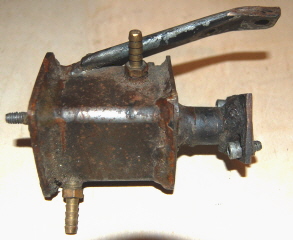
Water Cooled Intake Manifold. This Particular manifold was constructed using simple pipe, square tubing and plate. The water enters at the top of the unit and exits below. The upper bracket connects to the cylinder head for structural support.
As far as a carburetor is concerned it doesn’t know that air is being rammed into it and so it performs the way it was designed to function.
There is one problem that is most prevalent with this type of system and that is that where ever there’s a gasket seal on a carburetor or gas tank there is going to be pressure on it so it could leak. The way carburetors are designed they are to have vacuum on them at all times, therefore you don’t see leaks if anything air is sucked into the carburetor and not pushed out of it. Leaks manifest themselves at the bowl joints, at the throttle linkage, at the gas tank cap, and at the choke interface linkages.
Carburetors that do not lend themselves to being pressurized typically are the diaphragm style carburetors. The reason for this is that it diaphragm carburetor relies on the pulses from the engine and sometimes you might not be able to get the linkage between the pressurization of the engine and the pressurization of the carburetor to work out properly.
Some Briggs & Stratton carburetors do not lend themselves to pressurization and it mostly is because the way the metering jets are set up for not real adjustability. So what tends to happen is that the engine will run lean and will not be able to be supercharged.
In the event that you cannot use the carburetor that the engine was designed to have then you need to come up with another method to carburet the engine. The simplest method is to make your own intake manifold and use a carburetor that lends itself to being pressurized.
Fuel injection
Fuel injection is a method for administering fuel into the air stream going into the intake. There are various methods for a fuel injecting and they are:
– Mechanical fuel injection
– Meter plate fuel injection
– Electric metering fuel injection
– Electronic fuel injection.
Mechanical fuel injection is that which is normally found on a diesel engine. However that is not the only fuel injection that is mechanical. The old time Corvette engines had mechanical style fuel injection which is based on vacuum pressures. They are very prone to breakage or malfunction and therefore were not as reliable and never took off as a viable source of fuel injection.
The mechanical style diesel style direct fuel injection basically develops a pressure by using a pump on the fuel and then the fuel injectors are opened up using mechanical means. The pressure alternately could be increased causing a fuel injector to inject more or less fuel. This injection pressure would be increased at the pump by a metering unit.
The complexity of such units is that the pump itself requires tight tolerances and that the fuel injector must be metered using high-pressure lines from the pump.
The next method of developing fuel injection is using air mass flow plate. The flow plate measures the amount of air going into the engine and opens and closes a metering valve. Because the rate of flow going into the engine is proportional to the mass of air going around the flow plate the opening and closing of the metering valve is proportional and therefore the amount of fuel being delivered has a correspondence to the opening closing of the injector valve.
An approximate fuel flow can be developed using a relationship between the RPMs and fuel flow that is electronic and simple. The downside to this particular system is that it has a throttle lag.
Electronic fuel injection uses a number of sensing variables to map out an optimum fuel rate to maximize fuel burning. The simplest electronic fuel injection system only requires RPMs and throttle position. The more complex systems utilize ignition timing, fuel air mixture based on exhaust gases, intake air mass flow rates, and knock sensors in the head. All of the system are obviously maintained by a computer. The computer has a map that’s internally pre-programmed into the memory. The computer constantly matches up the parameters that are being sensed and goes to the map in the memory. The map then tells the computer how much fuel to meter at that particular location.
The map has been generated at the lab of the engine manufacturer. Newer engines sense on the fly and make up their own maps, however these rely heavily on maps that already exist. So extensive research and development needs to occur before the fuel injection system can be used.
Currently, there are not any fuel injection systems that are readily available for smaller engines. The method for metering gas using a fuel injection system must be improvised. Maps must be generated by the end-user.
The advantage of fuel injection is that you can maximize power at all rpm levels. The downside to carburetion is that the carburetors is an approximate metering of gas and therefore does not apply to all rpm and load levels. This can be most readily felt in the lower rpm ranges when power is needed.
Typically what designers will do is try to maximize fuel flow at the low RPMs therefore increasing the torque at the lower RPMs. This is achieved by using two carburetors. One carburetor dishes out a lot of gas at low RPMs and the other carburetor dishes out more fuel flow of the higher RPMs.
To Recap:
Just slapping a super charger on your engine is not the full picture. The supercharger will add pressurized air, but getting the air-fuel mixture into your engine with positive horsepower results is another matter.
Intercooling is designed to increased the air charge even more into your engine by increasing the air density. A supercharger has a downside in that it tends to add energy to the air charge causing the air to expand or decrease in density. This translates into less horsepower, or less combustion force.
The intercooler cools the air down increasing the density of the air charge. It provides positive horsepower results to both normally aspirated and supercharged engines. If you want a horsepower increase without spending a ton of money, use an intercooler set up to start.
Providing an increased pressured air-fuel mixture requires some carburetor tricks, regardless of what method you use.
There are two methods:
1. Suck air-fuel mixture through the supercharger and then into the engine
2. Ram air through the carburetor and into the engine
Sucking air through the supercharger requires a tight sealing environment. Any leaks and you will have the engine quitting on you all the time, not ideal for a low budget supercharger set-u.
Ramming air through the carburetor is the most cost effective method, but it too requires some sealing techniques on the gas tank, and the carburetor itself so that both units are pressurized. Care must be taken to avoid gasoline leaks, especially on the gas tank cap and the carburetor seals.
For more advanced and dynamic power range for a motor, a fuel injection system can be developed. This particular system is not for the timid but for the knowledgable go karter. If fuel injection is going to be used other engine design considerations should be performed as well, such as increased compression, overhead cam, high lift cam, forged crank, titanium connecting rod and a large capacity oil cooler system.
A carburetor for most go kart enthusiasts will do the job just fine, however compromised in overall performance will have to be endured. For example the engine will deliver good horsepower at 1300 to 3600 rpms, but really pale in the power curve in anything above 4000 rpms.
The opinions expressed in this article are just that, opinions. Engines are dangerous mechanisms and should be handled with care. They have spinning components and are extremely hot posing burn and flame hazards. Additionally, overpoweringand over revving an engine can cause it to flyapart and kill someone. The Go Kart Guru assumes you understand mechanics, the dangers associated with engines, go karting, and anything associated with motorsports. Any information taken from this article is your own responsibility, and the Go Kart Guru and its associates are not to be held responsible for any accident or injuries.
This article is copyrighted to Go Kart Guru.com and Go Kart Guru Blog.com Copyright 2009.