That is a strange title “Going around corners with mechanisms.”
What do I mean by that?
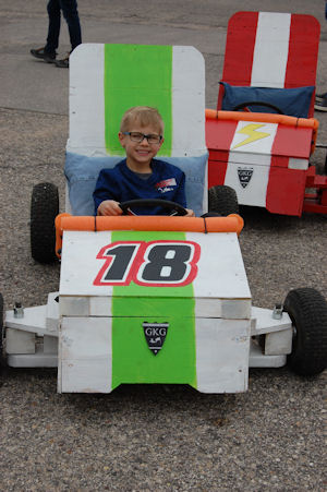
Sometimes what occurs when developing a go kart the logistics of connecting pedals to throttle system becomes challenging. The challenge usually comes in that the pedal is on the opposite side of where the mechanism is and so the linkage is not just a straightforward or straight shot back to the brake or the throttle.
For example: on a double wide go kart the brake system could possibly be on the passenger side of the go kart. The reason for this is that there is more space and it is easier to package the break system on that side.
Getting the proper forces from a pedal to the brake can be a challenge because now the brake system is on the far side of the go kart and the question is “How do you get those forces transferred to the others side of the go kart without using a cable?” Typically a cable may not be able to handle in the long run or the forces required for braking. The forces required for braking maybe in an upwards of 100 to 200 pounds in the linkage system.
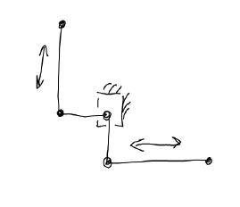
A Bell crank mechanism is designed to transfer motions to 90 degrees to the original motion
To overcome this conundrum there are several systems that can be used which are based on the bell crank system:
– The push pull system
– The pull pull system
The placement of the bell cranks dictates the direction of the system. Rigid connecting rods are required for the systems however if springs are used tension cables can be used instead.
The length of the bell crank arms dictates how much force is being transmitted. If all the radii are the same then the pull force will be the same as the pull force at the other end of the mechanism. The following formula can be used to calculate how much force will be transmitted through the mechanism. You can use the mechanism as a reducer or any multiplier of force.
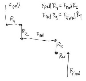
The variables are assigned to each of the components in the linkage.
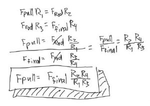
The formula for the bell crank mechanism. Change of the variables will result in force changes. Additionally, the angle of movement will change correspondingly. Generally speaking, a larger radius driving a small radius will require smaller initial movements for large output movements.
To determine the forces on the input and out put side of the mechanism plug in the lengths for each part of the linkage. Notice, the length of the rods is not in the equation, just the length of the radii of each of the bell cranks.
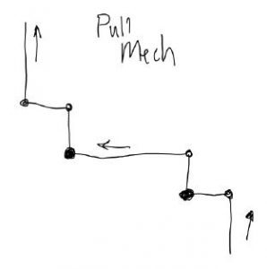
This particular set up is design to keep the direction of the original motions the same: just a transferred across a span
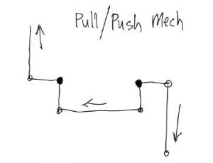
This mechanism reverses the original motion to be pushing instead of pulling
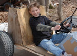
Below is an actuation mechanism that was using bell cranks to activate a blower system, or supercharger drive system. The mechanism consists of a handle pulling on a lever. The lever then in turn pulls on a crank mechanism which consists of a shaft and bell crank plates on either end of the shaft. The bell crank then in turn activated a lever mechanism which pushed up on the blower assembly. The blower assembly being pushed straight up would then tighten itself, or make the belt tighter therefore activating the blower, or supercharger. No springs are required for the system because gravity did all the work when the linkage was released.
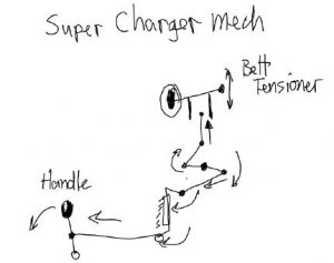
This is a linkage for activating a homemade supercharger on a go kart. The handle is pulled forward and as a consequence through the mechanism results in a upward motion that tightens the belt, or turns on the supercharger.
These type mechanisms can be used to activate throttles or brake systems. Also least it’s a mechanisms can be used to manipulate shock absorbers and suspension systems so that they are more compact.
For example: a bell crank mechanism can be used to make the shocks go horizontal on the frame or cross the frame so that the packaging is more compact.