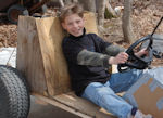
The main go kart frame consists of a piece of plywood and several two by fours sandwiched between the plywood panel’s. The seat is designed out of plywood and has multi-positioning capabilities so that different sized drivers can use the go kart.
The material requirements for the go kart are as follows:
- (5) 2 x 4 s
- one piece of 4 x 8 3/8 inch plywood
- two three-quarter inch bolts grade 5
- two sections of Axel three-quarter inch axle shafting
- several sections of pipe
- two bicycles
- number 40 chain, can use by chains if desire to save money
- two half inch bolts 7 inch long
- 2 inch PVC pipe for steering system
- small section of swing style chain
- wood glue
- half inch bolts 6 inches long
- half-inch washers
- U- bolts
- nylon rope
- 2 inch drywall screws
- 1 inch drywall screws
Tools Needed
- power drill
- circular saw
- Sabre saw
- Hammer
- adjustable wrench
- drill bits: quarter inch, three-quarter inch, half-inch: Spade bits for a larger bits
- C. clamps
Making the center frame section:
Using the plan transfer the layout on to 4 x 8 sheet of plywood. Make sure that the plywood is not heavier than 3/8 inch, but is not thinner than quarter inch. If you use plywood that is too thin than the frame will be too flexible and may twist and break especially during pedaling.
Mark all the relevant holes and drill the holes in each half of the plywood sections. This includes the seat sections as well. Make sure you drilled him as pairs so that when the system is assembled together the holes lineup. This is important for the seat system to work properly. Additionally, the holes are important for the rear axles assembly to work properly, so make sure that you drilled these as pairs.
Next, 2 x 4 sections per the drawings provided. Again drill the holes into the two by fours at the proper locations.
After all the pieces are cut out, take the larger center section halves and drywall screw them together. It is advisable to use glue to hold the halves together as well this provides an even more rigid center body section.
Mount the rear crossmember support plywood section to the rear assembly. Mount the support one by one by gluing/drywall screwing into the main body section. Insert the rear axle into the back section of the framework. Mount the Outrigger support boards to the crossmember plywood section. Be sure the axle is rotating freely before you lock everything down.
Take a bicycle and crank mechanism from the bike. This will require a hacksaw and perhaps a grinder. Next U-bolt the crank mechanism into the framework of the main body. Be sure to have ample support behind the crank so that the crank system is not twisting when forces are applied. An alternate method for mounting the crank mechanism is to mount the crank mechanism using standard u-bolts, however the crank mechanism is held in place with a slight weld on the U-bolt to the crank mechanism housing. This adds stiffness to the system. You may also find that a good wedge of wood provides the stiffness needed to keep the system from twisting.